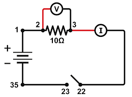
We shall discuss some techniques commonly applied in circuit design and analysis. These techniques include combining resistors in series or parallel, voltage division, current division, and delta-to-wye and wye-to-delta transformations. The application of these laws and techniques will be restricted to resistive circuits here. The laws and techniques are apply to real-life problems of electrical lighting and the design of dc meters.
OHM’S LAW
Materials in general have a characteristic behavior of resisting the flow of electric charge. This physical property, or ability to resist current, is known as resistance and is represented by the symbol R. The resistance of any material with a uniform cross-sectional area A depends on A and its length e.
R = ρ/A
where ρ is known as the resistivity of the material in ohm-meters. Good conductors, such as copper and aluminum, have low resistivities, while insulators, such as mica and paper, have high resistivities. Table 1. presents the values of ρ for some common materials and shows which materials are used for conductors, insulators, and semiconductors.
Resistivities of common materials.
Material Resistivity (Ὡm) Usage
Silver 1.64 × 10⁻⁸ Conductor
Copper 1.72 × 10⁻⁸ Conductor
Aluminum 2.8 × 10⁻⁸ Conductor
Gold 2.45 × 10⁻⁸ Conductor
Carbon 4 × 10⁻⁵ Semiconductor
Germanium 47 × 10−2 Semiconductor
Silicon 6.4 × 10² Semiconductor
Paper 1010 Insulator
Mica 5 × 10¹¹ Insulator
Glass 1012 Insulator
Teflon 3 × 10¹² Insulator
The circuit element used to model the current-resisting behavior of a material is the resistor. For the purpose of constructing circuits, resistors are usually made from metallic alloys and carbon compounds.
That is,
v ∝ i
Ohm defined the constant of proportionality for a resistor to be the resistance, R. The resistance is a material property which can change if the internal or external conditions of the element are altered, e.g., if there are changes in the temperature.
V = IR
This is mathematical form of ohm’s law, and it is measured in ohms (Ὡ)
R = V/I
1Ὡ = 1V/A
To apply Ohm’s law as stated, we must pay careful attention to the current direction and voltage polarity. The direction of current I and the polarity of voltage v must conform with the passive sign convention. This implies that current flows from a higher potential to a lower potential in order for v = IR. If current flows from a lower potential to a higher potential, v = −IR.
Since the value of R can range from zero to infinity, it is important that we consider the two extreme possible values of R. An element with R = 0 is called a short circuit. For a short circuit,
v = IR = 0
showing that the voltage is zero but the current could be anything. In practice, a short circuit is usually a connecting wire assumed to be a perfect conductor.
Example 1. An electric iron draws 2 A at 120 V. Find its resistance.
Solution
R = V/I = 120/2 = 60Ὡ
Example 2. Calculate the current I.
Solution
The voltage across the resistor is the same as the source voltage (30 V), the resistance of the resistor is (5)
I = V/R = 30/5 = 6A
NODES, BRANCHES, AND LOOPS
Since the elements of an electric circuit can be interconnected in several ways, we need to understand some basic concepts of network topology. To differentiate between a circuit and a network, we may regard a network as an interconnection of elements or devices, whereas a circuit is a network providing one or more closed paths. The convention, when addressing network topology, is to use the word network rather than circuit. We do this even though the words network and circuit mean the same thing when used in this context. In network topology, we study the properties relating to the placement of elements in the network and the geometric configuration of the network. Such elements include branches, nodes, and loops.
In other word a branches
Represents any two terminal elements.
A node is usually indicated by a dot in a circuit.
A loop is a closed path formed by starting at a node, passing through a set of nodes, and returning to the starting node without passing through any node more than once. A loop is said to be independent if it contains a branch which is not in any other loop. Independent loops or paths result in independent sets of equations.
Elements are in series when they are chain-connected or connected sequentially, end to end. For example, two elements are in series if they share one common node and no other element is connected to that common node. Elements in parallel are connected to the same pair of terminals. Elements may be connected in a way that they are neither in series nor in parallel. The voltage source and the 5-Ὡ resistor are in series because the same current will flow through them. The 2-Ὡ resistor, the 3-Ὡ resistor, and the current source are in parallel because they are connected to the same two nodes (b and c) and consequently have the same voltage across them. The 5-Ὡ and 2-Ὡ resistors are neither in series nor in parallel with each other.

